Memory Mapping
3.1 Overview
Zeal Video Board requires dedicated video RAM (VRAM) to store graphical data. Unlike many 8-bit systems, where VRAM is typically allocated from the main system RAM, ZVB includes its own internal RAM. This means the host system does not need to allocate or reserve any of its own memory for video purposes.
Since Zeal Video Board was originally designed as a coprocessor for Z80-based computers, it follows the Z80 bus segmentation with two different buses:
- The memory bus, using all the address lines
- The I/O bus, only using the lowest 8-bit lines of address.
To improve compatibility with systems that lack a dedicated I/O bus, all ZVB controllers and their registers are accessible via also accessible via the memory bus.
3.2 Memory Bus
Zeal Video Board requires approximately 80KB of internal memory, but due to alignment constraints and internal optimizations, this memory must be into a 128KB memory range.
It's important to understand that not all of the 128KB memory range is actually used. The memory is spread out, with some gaps between the parts that are used. Even though only about 80 KB is needed, the full 128 KB range must still be reserved by the host in the address space:
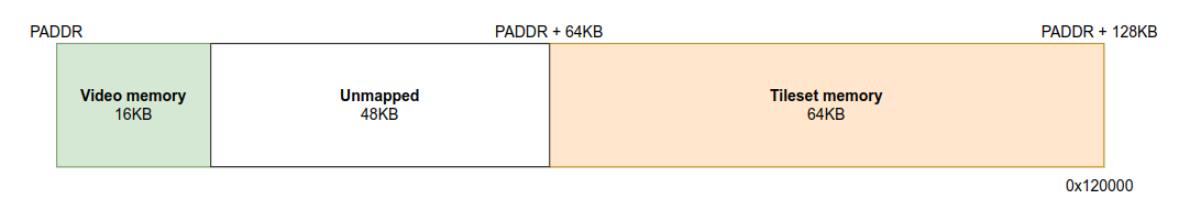
The video RAM memory starts at PADDR physical address. On boot and reset, PADDR is internally set to 0x100000 (1MB). For more details about how the physical address is calculated or how to mapped it on computers with a small physical address space, check the System Configuration chapter, section Physical address
Video Memory
The first part of the video memory, which is 16KB big, is organized as follows:
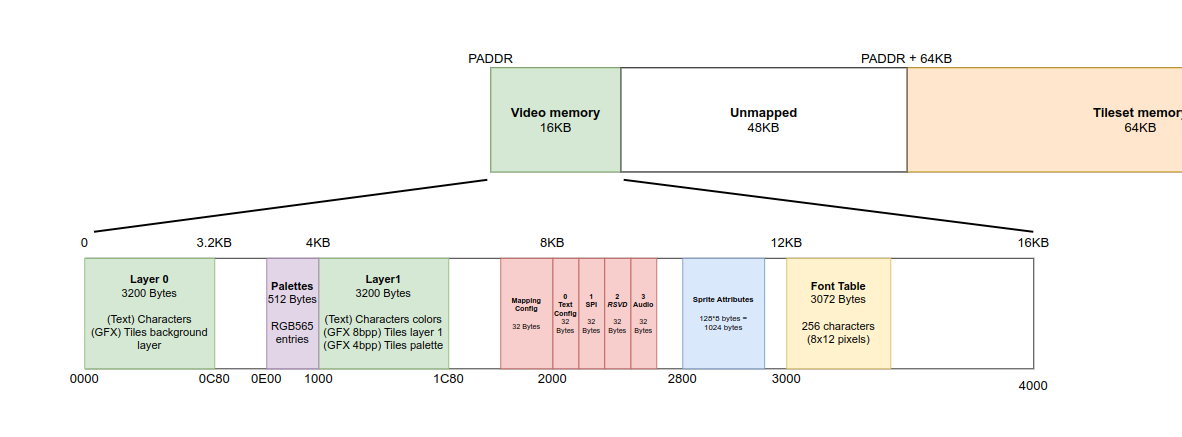
Note: The gaps between components is unmapped memory, the video board will not reply to any request performed there but they must not be used by any other hardware device.
The layer 0 and layer 1 tilemaps are mapped to offsets 0x0000 and 0x1000 respectively, both are 3200 bytes big. For more details about their usage and how they are organized, check the Tilemaps memory.
The red areas in the diagram represent I/O controllers that are also accessible through the I/O bus. For example, the System Configuration registers are mapped at offset 0x1FE0 in memory, but they are also available at I/O port address 0x80, as shown in the I/O Bus section below. As you can see, each controller occupies 32 bytes in the memory-mapped address space, but only 16 bytes on the I/O bus. This allows for additional features or extended functionality when accessed through memory.
All existing controllers, as well as future extensions, are mapped starting at offset 0x2000 and continuing up to offset 0x2800. This range allows for up to 64 peripherals, each occupying a 32-byte region. The starting offset of each controller is calculated as idx * 32, where idx is the index of the controller.
You can find the list of all implemented controllers in the System Configuration chapter, I/O Controllers section.
Note: As of this writing, no controller uses more than 16 bytes, so the extra memory space remains unused for now.
3.3 I/O mapping
To simplify and speed up access to the most common peripherals, the video board also maps itself on the I/O bus:
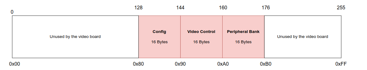
We can note that the first two modules are the same as the ones available on the memory map described earlier, the difference being that only the first 16 registers are visible on this bus (currently, no peripheral/module has reached this limit yet)
The third 16-byte module is the peripheral bank. It allows the host CPU to map any of the 64 peripherals that are located starting at offset 0x2000 in video memory. As said previously, only the first 16 bytes of each controller are accessible through this one. This design choice helps prevent the video board from occupying too much space on the I/O bus, which is already significantly smaller than the main memory bus.
This bank is configured by writing to the MAPPED_DEVICE register of the System configuration controller. See the I/O Controllers section for a list of valid values.