Getting started with Zeal 8-bit Video Board
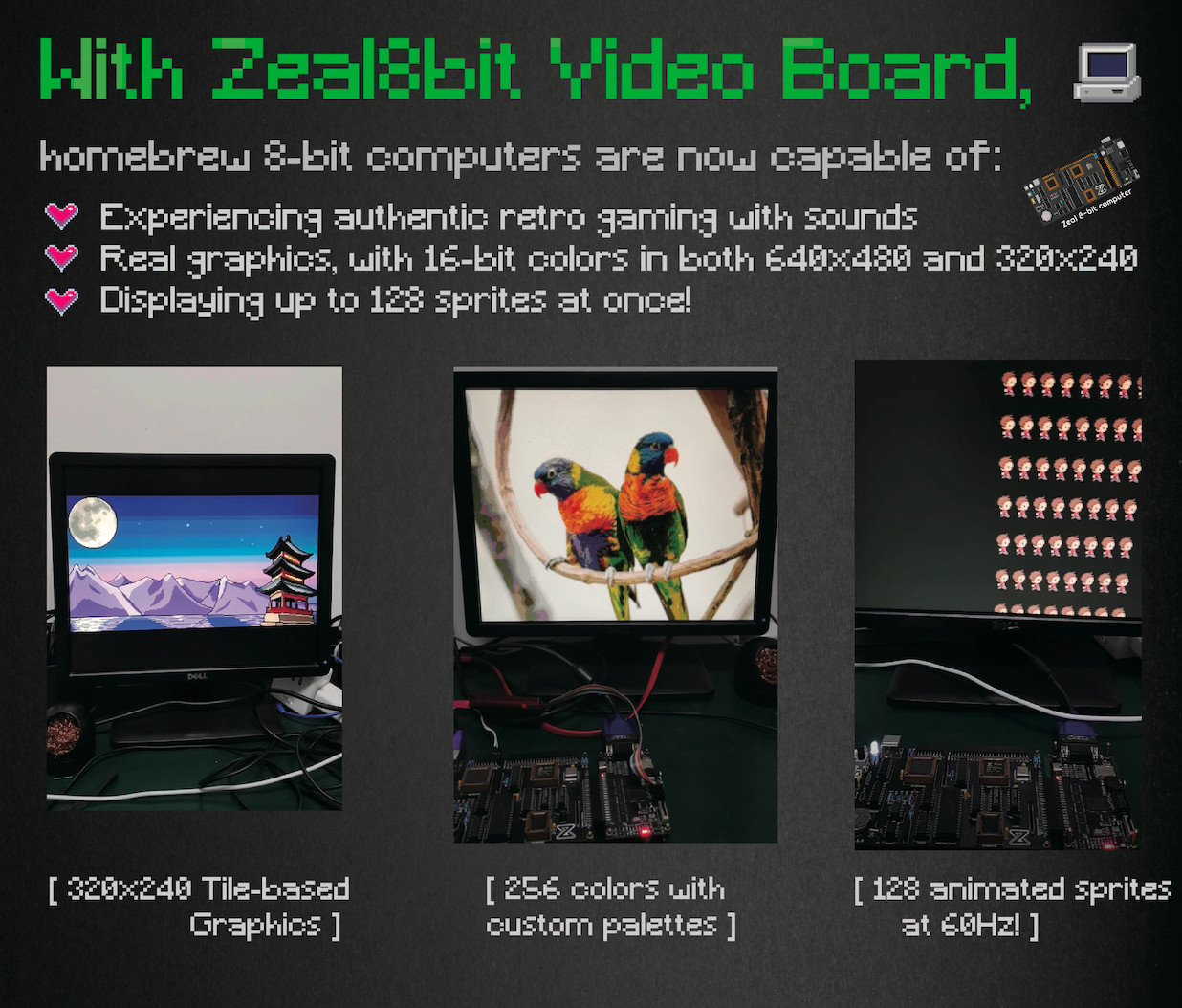
Enjoy modern retro graphics on your Zeal 8-bit computer or any other 8-bit computer right now thanks to the Zeal 8-bit video board!
The project Zeal 8-bit Video Board is part of another bigger project: the Zeal 8-bit Computer. Started in early 2021, the goal is to make a homebrew 8-bit computer that keeps the same simplicity of retro microcomputers, like the Commodore 64 or the ZX Spectrum, while providing more recent features like VGA graphics, TF card support or NOR flash storage.
If you want to learn more on Zeal 8-bit computer project, you can check the dedicated Tindie page, my official website zeal8bit.com or my Youtube channel Zeal8bit.
This edition of the Zeal 8-bit Video Board is made for developers, who are eager to port or develop games or graphical programs to it. Indeed, its rich features makes it possible to port almost any retro 8-bit game! Feel free to take part into the development, the community is getting bigger and bigger!
What is included?
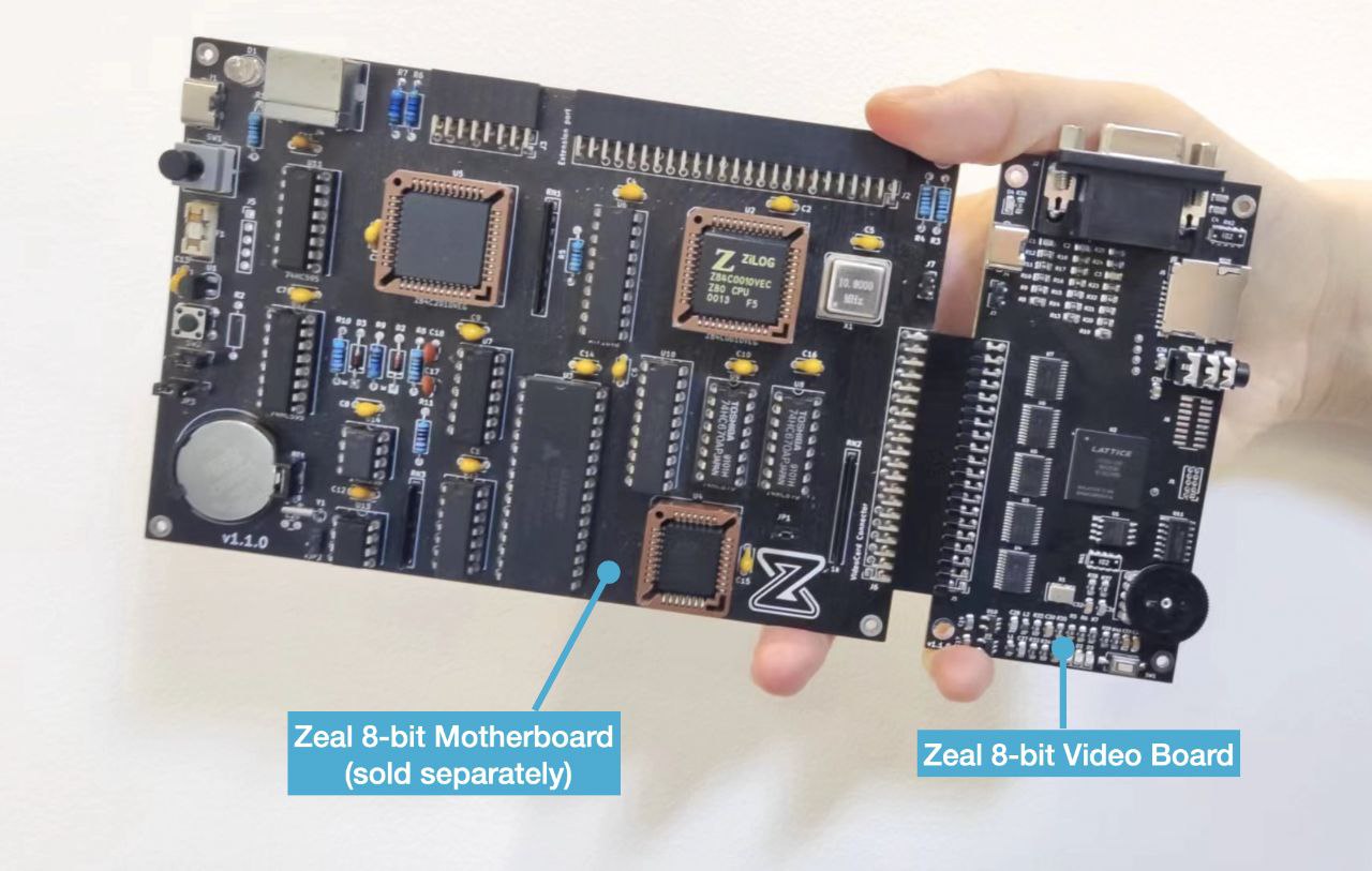
This product includes a pre-assembled, pre-flashed and pre-tested Zeal 8-bit Video Board. Its main components are the following:
- Lattice ECP5 FPGA
- VGA output, which can output up to 65536 colors
- 3.5mm jack audio output
- Volume wheel
- TF card port
- Standard 2.54mm 2x20-pin Bus connector to connect Zeal 8-bit Computer or any other 8-bit computer. The address, control and data lines are bi-directional (to let the FPGA perform DMA operations)
- Standard 2.54mm 1x2-pin DMA connector (unused for now)
- 1.1V, 2.5V and 3.3V regulators, the board only require a single 5V power supply (provided via the bus connector)
- 5V-to-3.3V level shifters, which make the bus connector 5V-tolerant
- One power LED
- Two general-purpose LEDs
- USB Type-C power input. Only used for development purpose, it should only be used if the bus connector is not connected since the latter must provide the 5V power input.
So, you will get:
- The Zeal 8-bit Video Board
- Two acrylic plates for protecting the board
- For Zeal 8-bit Computer owners, the 2x20-pin female video connector, that sits on the motherboard and wasn't populated when bought, will be given for free. Make sure to choose it in the accessories/options list and order with the same name as your former order.
What is NOT included?
- Zeal 8-bit Computer. This Z80-based 8-bit computer is sold separately, you can check its dedicated Tindie page.
- USB Power supply
- USB Type-C cable
Specifications
Here are the features of the board:
| Features | Details | Description |
|---|---|---|
| Video | Resolutions | 640x480, 320x240 |
| Color depth | 16-bit, RGB565 | |
| Video RAM | ~80KB of internal memory, no need for external RAM! | |
| Memory | 128KB of mapped memory (check memory mapping below) | |
| Text mode | 80x40 characters, wrapped when scrolled 40x20 characters, showing hidden characters when scrolled |
|
| 16 colors per character, for both foreground and background, taken from a palette | ||
| 8x12px per character | ||
| Font Table of 256 characters, 12 bytes per characters, customizable at runtime | ||
| Hardware cursor, scroll, wait-on-newline support | ||
| Graphics mode | Virtual resolution of 1280x640, only 640x480 or 320x240 can be visible at once | |
| Hardware scrolling to show hidden parts | ||
| Color palette (RGB565 colors) usable as a single 256-color palette or 16 16-color palettes Palette customizable at runtime |
||
| 16x16px tiles, 8bpp or 4bpp | ||
| 640x480px resolution, 40x30 tiles visible on screen 320x240px resolution, 20x15 tiles visible on screen |
||
| Up to 256 different tiles on screen at the same time in 8bpp mode (256-color palette) Up to 512 different tiles on screen at the same time in 4bpp mode (16 16-color palette) |
||
| One background layer, one foreground layer with transparency in 8bpp mode Single layer in 4bpp mode |
||
| Sprites | 128 hardware sprites, up to 40 sprites per scanline | |
| 16x16px tiles, taken from the same tileset than the other layers | ||
| Flip X and flip Y supported | ||
| Can be hidden behind foreground layer in 8bpp mode | ||
| Can be partially hidden in the screen borders | ||
| Audio | PSG | 4 voices |
| Each voice can generate triangle waves, sawtooth waves, squares waves or noise | ||
| Sample table | 256-byte sample table to generate arbitrary sound | |
| Configurable sample rate | ||
| SPI | TF Card | Interface up to 25MHz, configurable |
| Hardware FIFO | ||
| Miscellaneous | Recovery mode, to be able to upgrade the firmware from the 8-bit computer | |
| Modular memory mapping thanks to configuration registers | ||
| Hardware v-blank interrupt line | ||
| Hardware general purpose interrupt line (unused for now) |
Bus connector pinout
The bus connector is as follows (front view of it):
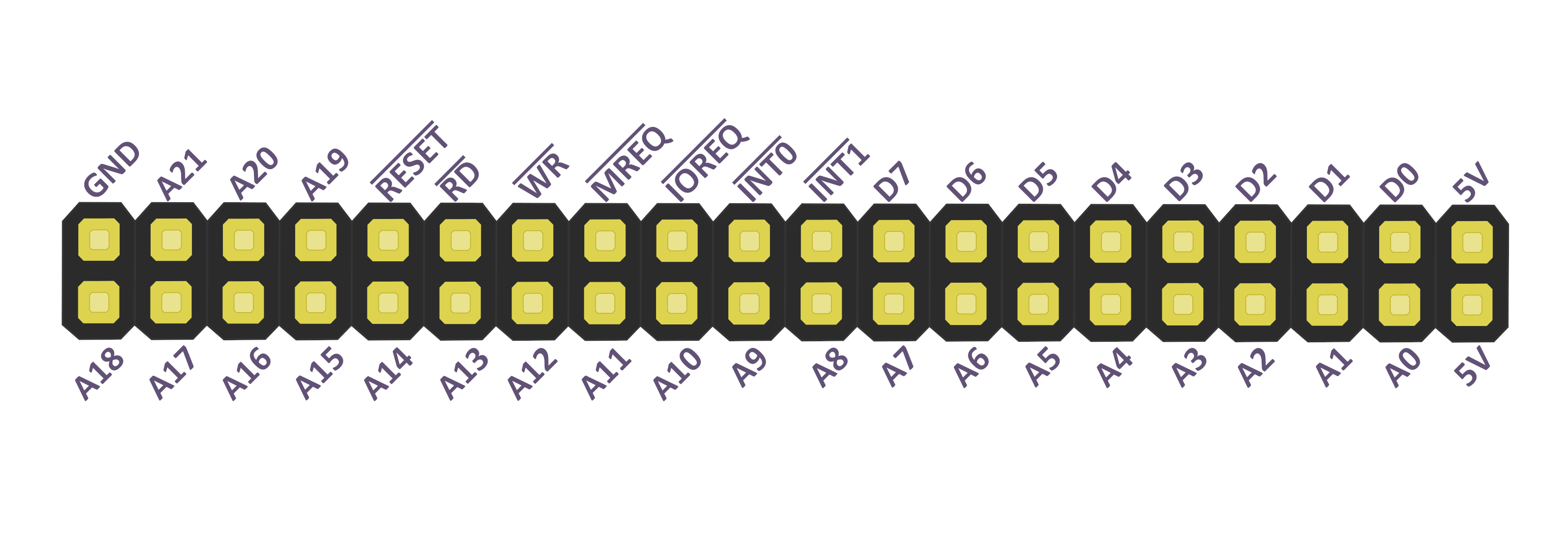
All signals marked with a bar on top are active-low.
| Pin | Direction | Description |
|---|---|---|
| A21-A17 | Bidirectional | Upper bits of the physical address of the 8-bit computer. On boot and reset, the FPGA maps its VRAM at 0x100000 (1MB). In other words, it will select itself if A21, A19, A18 and A17 are LOW and A20 is HIGH. As such, on computers that don't have such a big physical address space can consider these pins as chip selects. |
| A16-A0 | Bidirectional | Lower bits of the physical address of the 8-bit computer. Since the FPGA uses 128KB of memory, 17 bits are required. Check the memory mapping below for more information. |
| D7-D0 | Bidirectional | Data bus, input when the board is selected and WR is asserted (low), output when the board is selected and RD is asserted (low) |
| RESET | Bidirectional | Reset signal, active-low. This signal must be in an open-drain configuraiton. Even though this signal is bidirectional, the video board currently never asserts it itself. |
| RD | Bidirectional | Read signal, active-low. This signal is used to notify the board that a READ is requested by the motherboard. This is used in both IOREQ and MREQ. Even though this signal is bidirectional in hardware, the video board currently only uses it as input. |
| WR | Bidirectional | Write signal, active-low. This signal is used to notify the board that a WRITE is requested by the motherboard. This is used in both IOREQ and MREQ. Even though this signal is bidirectional in hardware, the video board currently only uses it as input. |
| MREQ | Bidirectional | Memory request signal, active-low. This signal is used to notify the board that a MEMORY REQUEST is requested by the motherboard. This follows the Z80 bus segmentation with a memory bus that makes us the use of all the address lines, and an I/O bus that only makes the use of the lowest 8 address lines (8-bit). Even though this signal is bidirectional in hardware, the video board currently only uses it as input. |
| IOREQ | Bidirectional | I/O request signal, active-low. This signal is used to notify the board that an I/O REQUEST is requested by the motherboard. During this request, only the lower 8-bit of address will be taken into account. For 8-bit computers that don't have such bus and only have a memory bus, this signal can be hardwired to HIGH. All the I/O modules can also be accessed via the memory bus. Check the memory mapping below for more information. Even though this signal is bidirectional in hardware, the video board currently only uses it as input. |
| INT1 | Output (3.3V) | General purpose interrupt signal, active-low. This output signal notifies the motherboard when a peripheral has a pending interrupt. It is currently not used but it is planned to have SPI, sound, timer and graphics interrupts. This line must NEVER be wired to a voltage higher than 3.3V to prevent damaging the FPGA! |
| INT0 | Output (3.3V) | V-blank interrupt signal, active-low. This output signal notifies the motherboard that the display component just entered v-blank state. This line must NEVER be wired to a voltage higher than 3.3V to prevent damaging the FPGA! |
Memory mapping
As stated above, The video board follows the Z80 bus segmentation, which means that there are two different buses: the memory bus, using all the address lines, and the I/O bus, only using the lowest 8-bit lines of address. However, keep in mind that the components accessible via the I/O bus can also be accessed via the memory bus, making it possible for 8-bit computers with only a single bus to use all components.
IMPORTANT: the effective VRAM we are talking about here is internal to the video board, it is not required for the 8-bit computer/motherboard to provide any RAM
Memory bus
Let's start with the mapping on the memory bus:
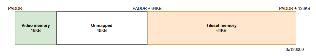
The video board memory start PADDR physical address. On boot and reset, PADDR is internally set to 0x100000 (1MB). In other words, the board will enable itself if A21, A19, A18 and A17 are LOW and A20 is HIGH. This can be configured with a register write, so please note that PADDR is always aligned on 128KB.
Video memory
The first part of the memory, which is mapped to the first 16KB, is organized as follows:
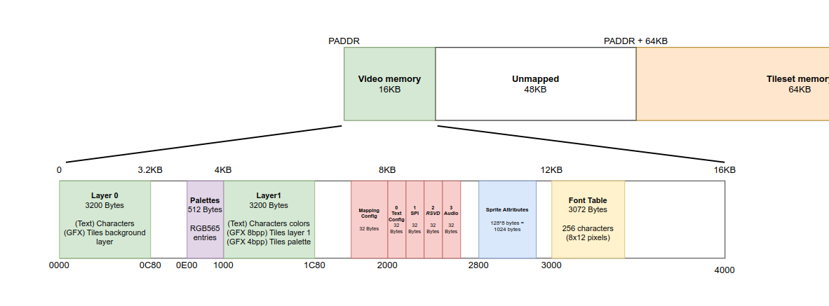
Note: the blanks between components is unmapped memory, the video board will not reply to any request performed there but it must not be used by any other hardware.
The first 3200 bytes are allocated to the Layer0, which is a write-only memory representing:
- In text mode: 80x40 characters. Each character is 8x12px big. In 40x20 text mode, only 1/4 of them will be shown at once, hardware scrolling can be used to decide which part to show.
- In both graphics modes: 80x40 background tiles in graphics mode. Each byte represents an entry, a tile, from the tileset memory (0-255). Note that not all of them will be visible at the same time, hardware scrolling can be used to decide which part to show.
The next component, mapped at 0xE00 is the write-olnly color palette, where each entry is a little-endian 16-bit word representing an RGB565 color. Bytes can be written independently from each other in this table. This palette can be interpreted as 16 palettes of 16 colors in graphics 4bpp mode. In text mode, only the first 16 entries will be taken into account. On boot (not reset), this table will be pre-loaded with the VGA/Mode 13h 8-bit color palette.
Right after the palette is the Layer1, which is also write-only and represents:
- In text mode: 80x40 characters color attributes in text mode. Each byte represents two colors, the high nibble (4-bit) is the background color and the lowest nibble is the foreground color. For example, byte
0xF2represents a character with color 15 as its background and color 2 as the character color. In 40x20 characters mode, this is still valid, it is possible to set the colors of hidden characters, before they are even shown on screen. - In 8bpp graphics mode: 80x40 foreground tiles. Same as the layer0.
- In 4bpp graphics mode: attributes for the layer0 tiles. For each byte, the lowest bit represent the highest bit of the tile entry index, while the highest 4-bit represent the palette to use (0-16). For example, if entry number 10 is
0x21, the index of the tile to show will be(1 << 8) | layer[10]and it shall be drawn with the palette of index2. This lets us have different 512 tiles in this mode, and even draw the same tile several times on screen but with different colors.
After the Layer1 comes the Mapping config which controls where the video board is be mapped on the physical address space. It also controls which peripheral is mapped to the I/O bank. See below for more information about this peripheral.
Each peripheral or future extension will be mapped right after, between 0x2000 and 0x2800. Each of them will be given 32 registers/bytes. We can have up to 64 peripherals in that space.
For more information about each of these peripheral, check the description below.
The sprite attributes memory starts at offset 0x2800, it is representing an array of 128 attributes, each of them being 8 bytes:
![]()
- The first 16-bit word (little-endian) is the Y position of the sprite. NOTE: this position is translated by 16px! In other words, to show the sprite at the top of the screen, this register must be written with value
16. Simiarly, wirting8to this register would result in a sprite that is half hidden/half shown at the top of the screen. Thus, a value of 0 would completely hide the sprite. - The next 16-bit word is the X position of the sprite. Just like the Y coordinate, it is also transalted by 16 pixels. So writing a 0 here will result in a sprite not being shown.
- The next byte is the flags attributes, containing, from MSB to LSB: the 4-bit palette index (4bpp only), flip X transformation, flip Y transformation, behind foreground (8bpp only), and tile index highest bit (4bpp only)
- The following byte is the tile index (lowest 8-bit in 4bpp)
- The next 2 bytes are reserved for now.
A few remarks on the sprites:
- The sprite attributes memory is write-only.
- They only visible in graphics mode, they won't be shown in text mode
- They are not affected by screen scrolling
- They are always 16x16px big
- They share the same tileset as the
layer0andlayer1 - Despite being organized as a 16-bit word memory, it is possible for the CPU to only write a single byte without affecting the other one
The final area of the video memory region is the font table, on characters memory. There are a total of 256 characters, each character is 8x12 pixels big and thus utilizes 12 bytes. Characters are encoded as bitmaps, where one line is encoded by one byte: bit 1 is a foreground pixel, 0 is a background pixel. This part of memory is r/w, so it can be read by the CPU (mainly to backup the font).
For example, the character 0 can encoded as 0x00, 0x3c, 0x42, 0x42, 0x42, 0x42, 0x42, 0x42, 0x42,0x3c, 0x00, 0x00:
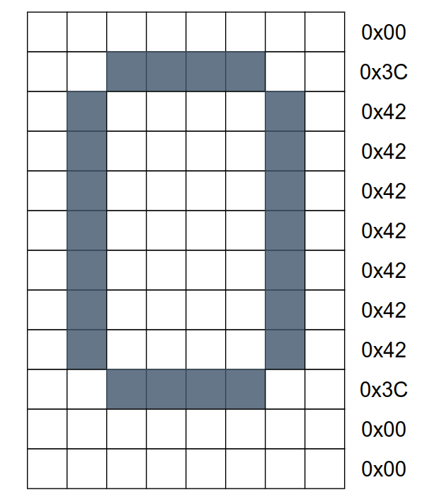
These bytes must be stored starting at offset 0x30 of the table to respect ASCII encoding.
On boot (not reset), the font preset in the font table is the BigBlue character set, created by VileR, licensed under the Attribution-ShareAlike 4.0 International. No changes have been made to this font.
Tileset memory
The upper half (64KB) of memory mapped for the video board is the write-only tileset memory. In text mode, this memory is not used at all, writing to it is still possible or course.
In 8bpp graphics mode, each tile is 256 bytes big, and each byte represent a color index to get from the color palette. This gives us a tileset memory of 256 x 256 = 64KB.
In 4bpp graphics mode, each tile is 128 bytes big, each byte represents two adjacent pixels. In fact, each nibble represent a color index to search in a 16-color/4-bit palette. The palette is either specified in the Layer1 or in the sprite attributes. This means that a single tile can be shown with different colors on screen. Since the tileset memory is write-only, you must be aware that each byte write will affect two pixels in this mode!
The tileset memory is organized on a per-tile basis, so the first 256 bytes (128 in 4bpp) represent the first tile, tile 0. In 4bpp mode, the higher nibble represents the first pixel, the lower nibble represents the second pixel.
This memory can be written at anytime, even if the video controller is not in a H-blank or V-blank.
I/O mapping
To simplify and speed up access to the most common peripherals, the video board also maps itself on the I/O bus:
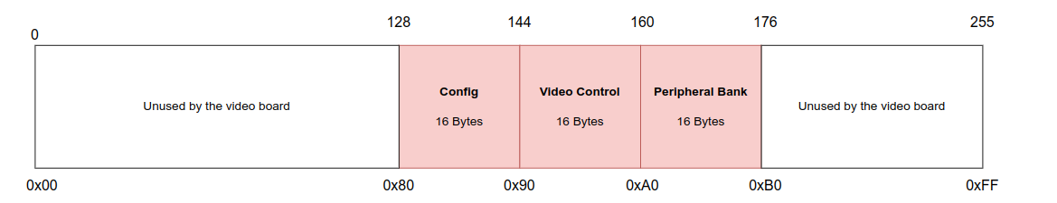
We can note that the first two modules are the same as the ones available on the memory map described earlier, the difference being that only the first 16 registers are visible on this bus (currently, no peripheral/module has reached this limit yet)
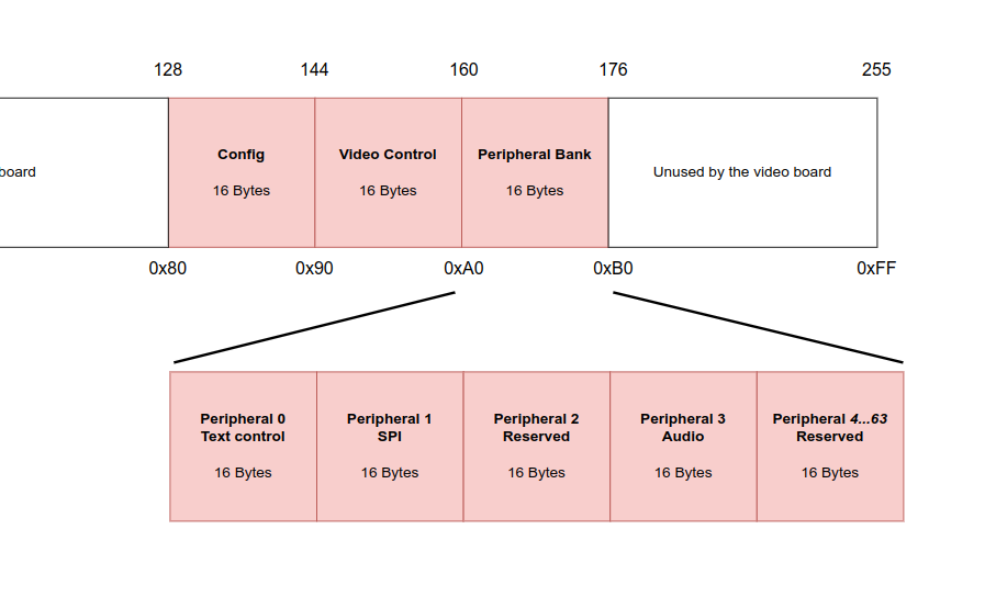
The third 16-byte module is the peripheral bank, it lets the CPU maps any of the 64 peripheral that are mapped at 0x2000 on the main video memory. Again, only the first 16 byte/registers will be shown. This design choice was made to prevent the video board from taking too much space on the I/O bus, which is already very small compared to the main memory.
This bank can take the show the following peripherals:
The peripherals won't be explained in details, with each of these registers here, but keep in mind that they will be documented in a dedciated document, and will also be present in header files that are used by Zeal 8-bit OS. You can already find a few details here: video_h.asm
A brief description for each of them:
- Config module can be used to configure the physical address of the video board (
0x100000by default) and the peripheral to map to the peripheral bank. It also contains registers with the current firmware version and a few general-purpose scratch registers - Video control module can be used to switch the video mode (text mode, graphics, etc...) or modify the current scrolling values in both X and Y for each layer in graphics mode. Layer0 and layer1 can have different scrolling values. It also has registers for getting the current raster location on screen, as well as some bits for the interrupts.
- Text peripheral contains register that can control the text mode. It can enable/disable the cursor, configure its blink speed, its shape, its colors. It can print a character on screen, it can set the text scrolling values, set the current color. It also has registers to configure the behavior of the screen when the limit in reached (scroll or wrap).
- SPI peripheral is a simple controller that is used to communicate with the TF card. It has a FIFO that can be filled and send on the bus on demand.
- Audio peripheral has registers to control everything related to audio: enable the sound voices, the sample table, set the master volume, set the waveforms, etc...
Using Zeal 8-bit Video Board
If you already have a Zeal 8-bit Computer, you will need to connect the video board on the motherboard's video connector. If this port is not populated, you will need to solder a standard 2.54mm 2x20pin connector (90 degrees). This part will be sent for free if you select it in the accessories list when ordering your Zeal 8-bit Video board.
Afterwards, you will need to update your flashed Zeal 8-bit OS to install the video-enabled version that can be compiled from source: https://github.com/Zeal8bit/Zeal-8-bit-OS
If you need assistance doing this, feel free to contact me or join our Discord server.
It is also possible to update the flashed Zeal 8-bit Bootloader which now has full support for the video board. You will find instructions on the official website of Zeal 8-bit project
Upgrading Zeal 8-bit Computer to use the Video Board
If you already own a Zeal 8-bit Computer that is currently using UART for all the standard outputs, you will need to upgrade the bootloader and/or the system to let them incorporate the video driver. Indeed, since version 1.3.0, Zeal 8-bit Bootloader supports both video as the standard output and the PS/2 keyboard as the standard input. Thus, you will need to upgrade the bootloader to this version to have these features.
The bootloader can be compiled from source, or it can be downloaded as a ready-to-flash binary file in the official release page.
This version of the bootloader also integrates a feature that let's you upgrade the firmware of the video board without the need of an external flasher.
Upgrade Zeal 8-bit Bootloader
IMPORTANT: upgrading the bootloader is risky, make sure to follow the instructions correctly!
The procedure to upgrade the bootloader is as follows:
- Download the latest bootloader binary file
- Make sure to check the integrity of the downloaded file (with
sha1sum) - Connect the Zeal 8-bit Computer to a host computer via UART, 57600 baud
- Power on your Zeal 8-bit Computer
- Enter bootloader menu
- Select
Flash/Program the ROM(foption) - Set the destination address to
0as the bootloader resides at address 0 on the NOR flash - Set the file size of the downloaded file in HEXADECIMAL
- When the bootloader asks
Please send file...: open a terminal on your host computer, make sure to configure the UART as raw. This can be done via the commandstty -F /dev/ttyUSBx 57600 raw, wherexmust be replaced with the proper device of your USB-to-TTL adapter. Use the commandcat bootloader_v1_3_0_video_stdout.bin > /dev/ttyUSBxto send the binary file. You will find more information about sending files to the bootloader on the Getting Started page.
If everything went well, the board will reboot and the video board should start displaying the bootloader (for 3 seconds before booting the OS).
Some VGA screens take more than 3 seconds before displaying the first frames, so it is possible to miss the video output of the bootloader. In that case, to be sure that everything is working, you can reboot or reset the motherboard and press ESC key on the keyboard to enter the bootloader menu, which doesn't have a timeout.
If flashing failed, the board will not boot anymore, and it will be necessary to use an external flasher, like a TL866 or an Arduino for example.
Upgrade Zeal 8-bit OS
Similarly, Zeal 8-bit OS also support the video board for the standard output. It is highly recommended to compile the system from source.
The procedure to flash the compiled OS binary is the same as the one for the bootloader above with the following differences:
- The OS binary to flash must contain both the OS binary and the romdisk image. The OS project will generate an
os_with_romdisk.imgfile, this is the one to flash! - The destination in NOR flash must not overwrite the bootloader, which starts at address
0x0000. It is recommended to use0x4000for the OS destination. - When compiling the OS, you must specify the physical address of the OS on flash via the
menuconfigin menuZeal 8-bit Computer configuration > Physical address of the kernel. This value must match the address that will be passed to the bootloader when flashing. In other words, I recommend using0x4000.
Examples and demos
Zeal 8-bit Video Board official Github project contains examples:
- Audio Sample Table - example of playing audio samples
- CRC32 - Generate CRC32 Sums using ZVB crc32 controller
- Flag - Simple example rendering the French Flag using colored tiles
- Hello World - Colored Text demo written in Assembly
- Parrot - Display a bitmap image
- Snake - Simple Snake clone for Zeal 8-bit Computer
- Sound - Examples of Square, Triangle and Sawtooth waveforms using Sound controller
- Sprites Demo - Demo showing how to render and animate Sprites
- Tilemap - Demo of Tilemaps
Some of my Youtube videos also show the capabilities of the video board: