Getting started with Zeal 8-bit Computer
Disclaimer
In this short article, we'll see how to get started with the Zeal 8-bit computer, from how to power it on to how to actually use it. This guide is not meant to be a complete documentation for the computer, nor is it a detailed technical reference manual. In case you have any questions, suggestions, or you simply need help, you can contact me either by email (check the About page) or on the Discord server.
Soldering the computer (kit only)
If your Zeal 8-bit Computer came as a kit, you will need to solder it first, you simply need to follow the Soldering Guide for Zeal 8-bit Computer.
Preparing the computer
Before powering on the board, let's review what is needed:
1. Zeal 8-bit computer motherboard
You will need to adjust some jumpers on the motherboard to start with. If you don't have the video card connector populated, or any video card connector plugged in, make sure to put the jumper caps on JP3 and JP4 on the far right pins (when the board is oriented with the coin-cell battery holder to your lower-left), as the photo below demonstrates:
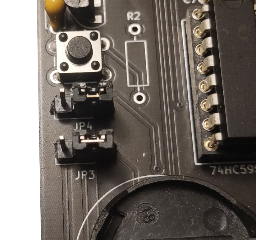
This will disconnect the V-Blank and H-Blank pins of the video card connector from the Z80 PIO I/Os. These I/Os will be connected directly to 5V.
By default, the ROM on the motherboard is a 256KB NOR Flash memory (component U4) and the jumper JP1 has no jumper cap on. If you have modified the board to use a 512KB ROM instead, connect a cap on that jumper.
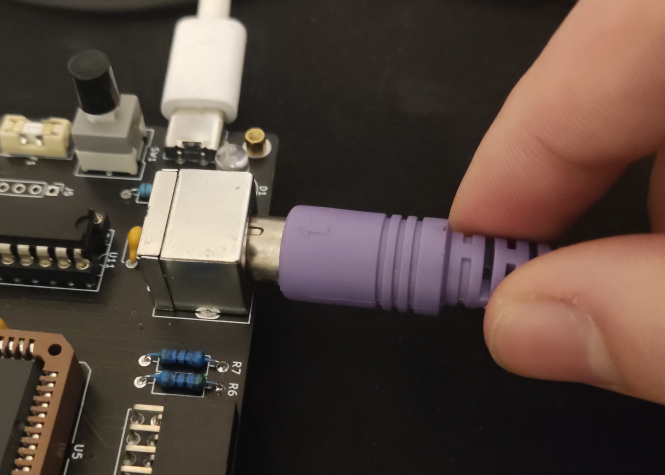
2. USB-to-UART / USB-to-TTL adapter
As the Zeal 8-bit computer currently doesn't have a video card available, it has been configured to use UART for standard output. In order to get this output, you will need an adapter or a UART-capable device connected to it. Here is an example of a USB-to-TTL adapter:
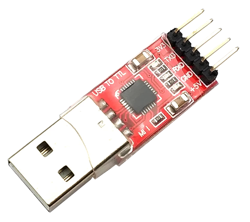
This will provide a monitor interface through a USB connection to a host computer (such as a laptop running Windows or Linux). Characters will be sent over USB to the host computer, which will be running terminal emulation software to present the received characters.
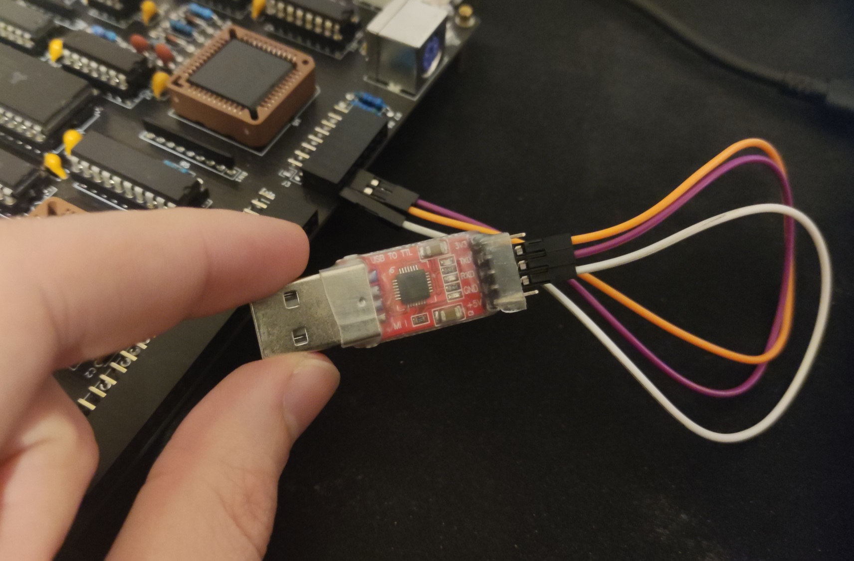
To connect the adapter, you must connect:
- The adapter's RX pin to the board's TX pin
- The adapter's TX pin to the board's RX pin
- The adapter's GND pin to the board's GND pin
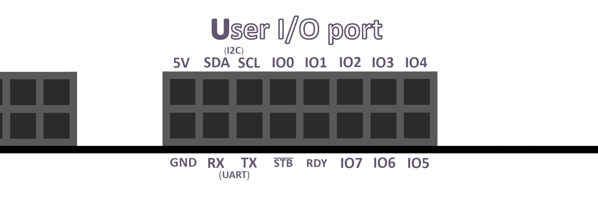
You will find the board's RX and TX on the 16-pin user port (J3), at the bottom left. Here is a front-view of that port:
After plugging in the adapter, you will get a result similar to the following:
The default serial configuration used by Zeal 8-bit Computer software is 8N1 (8-bit data, no parity bit, 1-bit stop) at 57600 baud.
3. PS/2 Keyboard
The current version of Zeal 8-bit OS doesn't support keyboard input through the UART, so you will need to plug in a PS/2 compatible keyboard into the J4 connector to fully use the OS.
It is not recommended to plug in or unplug PS/2 devices, including keyboards, once the computer is running. They must plugged in before powering on the computer.
4. Real-Time Clock
In order to activate the Real-Time Clock (or RTC) component, you need to insert a CR2032, CR2025 or CR2016 inside the socket BT1 located at the bottom left of the board. This battery powers the RTC's memory in order to preserve the time when the computer is powered off.
The Real-Time Clock is connected to the processor, and the system in general, through the internal I2C bus.
If no battery is present, the component will not respond to any I2C request. If an empty (drained) battery is plugged in, the RTC will work properly when the system is powered up and responding to all the requests, but it will not save the parameters when the board is powered off.
When putting in a new battery, first insert the left side and then push on the right side to insert it completely in the socket.
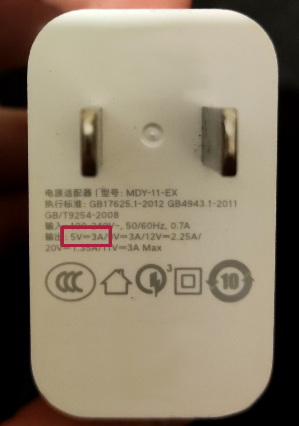
5. Power source
You will need a stable 5V source in order to power the board. A phone adapter should work without any problem, ideally, it should deliver at least 1A since the fuse present on the board allows up to 1A. This current requirement also depends on the devices you may plug into the board itself, via the extension port or user port.
Opening the monitor
We are almost ready to power on the Zeal 8-bit computer. Before we do, we need to start a terminal emulator on the host computer that will receive the serial output being sent to be displayed. Let's see how to do this.
Linux
After plugging in the USB-to-TLL/USB-to-UART adapter, it should be possible to see the adapter in the /dev folder. Search for it's name with:
ls /dev/ttyUSB*
If no entry is available, it may have another name, check with:
ls /dev/ttyACM*
If it is still not available, you will need to install the drivers for your adapter. Check the manufacturer's page or the datasheet for your device.
Once you have this special /dev/ttyUSB node in your system, we can continue. In this guide, we will assume the node is /dev/ttyUSB0, you will need to replace this with your actual device name in the commands that follow.
In order to be able to communicate with the ttyUSB, your user must be part of the dialout group. Check the groups you belong to with the command:
groups
If you are not part of the dialout group, type the following command:
sudo adduser $USER dialout
You will need to reboot your computer after this.
We are ready to communicate through the TTY now! On Linux, several terminal programs are available to open a serial monitor, let's see two of them: picocom and minicom.
picocom
Let's start by installing picocom. This can be done through the package manager. For example, on Ubuntu/Debian, type the following command:
sudo apt install picocom
After a successful installation, it is possible to execute it while specifying the baudrate and the node with the following command:
picocom -b 57600 /dev/ttyUSB0
The first lines should be as follow:
port is        : /dev/ttyUSB0
flowcontrol    : none
baudrate is    : 57600
parity is      : none
databits are   : 8
stopbits are   : 1
You are good to go!
minicom
If you prefer to use another monitor, you can use minicom. You can also install it through your package manager. For example, on Ubuntu/Debian, type the following command:
sudo apt install minicom
After a successful installation, it is possible to execute it while specifying the baudrate and the node with the following command:
minicom -b 57600 -D /dev/ttyUSB0
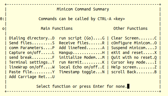
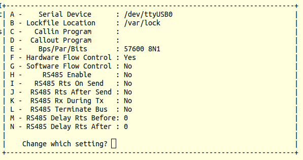
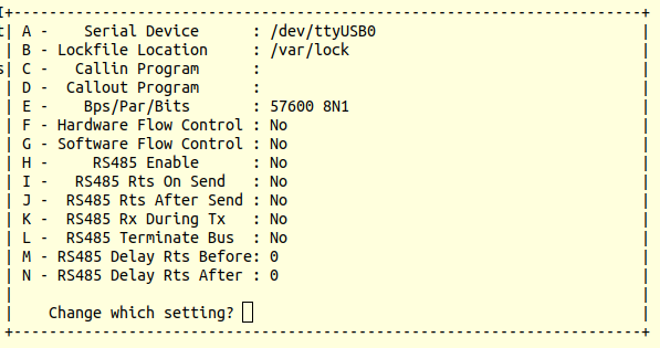
By default, minicom enables the hardware flow control and this needs to be disabled. You need to open the configuration menu with:
- Press Ctrl-A then Z
- Press o (letter o, not zero)
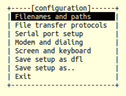
- Select "serial port setup"
- Press f
- Enter to validate the change, then escape to return to the monitor
You are good to go!
Windows
On Windows, it is necessary to install the drivers for your USB-to-UART/TTL adapter too. This is dependent on your device.
Plugging in the USB TTY device should cause Windows to recognize it as a COM port. Once recognized, you can open a terminal emulator. Let's see two of them for Windows: Tera Term and Putty.
Tera Term
First, start by installing Tera Term on your computer, check their official page to download and install it.
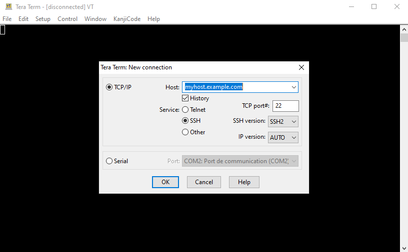
- After installing it, execute Tera Term:
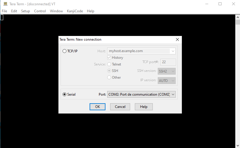
- Click on "Serial", specify the COM port corresponding to the USB adapter
- Press "Ok", the window should close itself
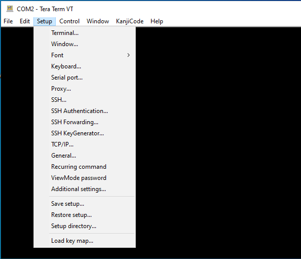
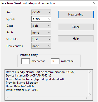
- Click on "Setup" and then "Serial port..." button from the menu
- Specify "57600" in from the baudrate menu and click "New setting"
You are good to go!
Putty
First, start by installing Putty on your computer, check their official page to download and install it.
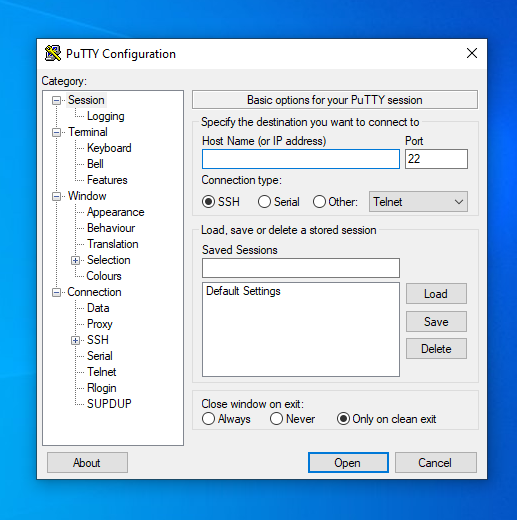
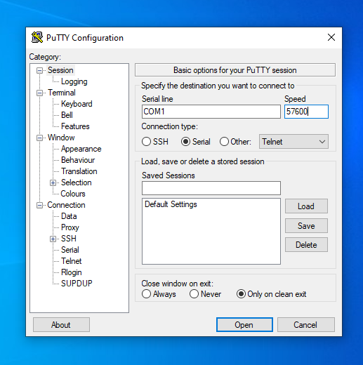
- After installing it, execute Putty:
- Click on "Serial", specify the COM port corresponding to the USB adapter, and fill the speed with 57600
- Click on "open" button at the bottom
You are good to go!
Power on the Zeal 8-bit Computer!
Bootloader version 1.0.0 and below (showing a hash as a version, e.g. 0b331cc) has a bug in their "test" feature. Launching a hardware test will corrupt the ROM sector (4KB) starting at address 0x4000, which, by default, contains Zeal 8-bit OS.
If you happen to have such bootloader version, upgrade it to a version newer or equal to 1.1.0, or, avoid using the hardware test feature.
It's time to fire up Zeal 8-bit Computer, simply press the big switch SW1.
As soon as you press it, you should see the bootloader message in the monitor:
Zeal 8-bit Computer bootloader 0b331cc


Press any key to enter menu. Booting automatically in 5 seconds...
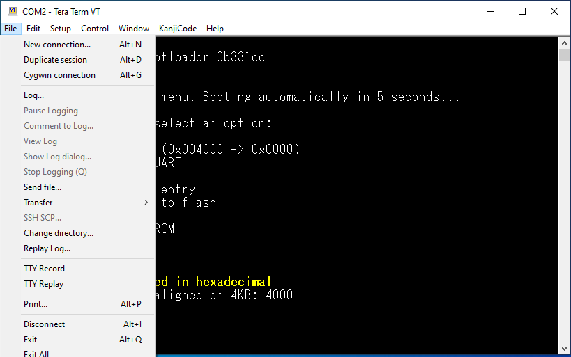
If no key in sent through the UART (no key pressed on the host computer), the bootloader will automatically boot its first OS entry. For the moment, we can take a look at the bootloader menu by pressing any key. We get the following menu:
Entering menu. Please select an option:

1 - Boot Zeal 8-bit OS (0x004000 -> 0x0000)
p - Load program from UART
a - Add a new entry
d - Delete an existing entry
s - Save configuration to flash
b - Change baudrate
f - Flash/Program the ROM
t - Test hardware
The first letter of each line represents the key to press to activate the feature described. Here is an explanation for each feature:
- 0 to 9: The bootloader supports up to 9 entries, which are programs/systems that can be booted. In the example above, only one entry is present: Zeal 8-bit OS. The numbers between the parenthesis represent the physical address (in ROM) and the virtual address respectively. In the output above, Zeal 8-bit OS is flashed at address 0x4000 in the ROM, it will be mapped at virtual address 0x0000 when booted.
- p: A program can be sent through UART, it will be booted directly after being sent. This is handy for development as it is not needed to flash the NOR flash to test a program.
- a: Add a new entry that can be booted by the bootloader. This submenu will ask for the physical and virtual addresses of that new entry, but the system itself must be flashed separately with feature f.
- d: Delete an existing entry. It is not possible to delete all entries, there must be at least one existing entry at any point in time.
- s: When adding and deleting entries, the changes are saved to RAM. In order to flush the changes to the ROM, this feature must be executed.
- b: Change the baudrate of the bootloader for the current session only.
- f: Flash any part of the ROM/NOR flash with any binary file. The changes are directly written to the flash, no need to flush. It is possible to use this feature to update the operating systems installed on the flash, and even to update the bootloader itself.
- t: Small program that tests the hardware, which includes the RAM size, the ROM size, the I2C EEPROM, the I2C RTC, and the PS/2 keyboard.
Hardware test
As described above, one of the feature of the bootloader is to test the hardware. This small program will not only try to communicate with the peripherals on the board but it will also try detecting the size of each.
To launch a hardware test, press t from the bootloader menu. You should see something like this:
Enter your choice: t
Testing the hardware:
MMU......................Success
NOR FLASH................256KB detected / Success
RAM......................512KB detected
I2C EEPROM...............64KB detected
I2C RTC..................Success
Date & Time..............35 20 16 06 04 03 23 00
PS/2 Keyboard............Press q
Some line may differ however depending on your configuration. For example, the I2C EEPROM line can also be 32KB on the board that have the 24LC256 EEPROM chip.
The Date & time may also show the following lines:
Disable: the RTC chip is active and responding to the CPU but it is in idle mode. The bootloader automatically sends an "enable" command to the RTC after printing this line. Launching the hardware test again should show the RTC value. If that's not the case, the installed battery must be replaced.Error: the RTC chip was not detected as it didn't reply to the CPU requests. This can happen if a battery is not installed (the BAT+ pin is left floating, which is not a valid state for the RTC chip). If you still want to use the RTC without a battery, you can connect the BAT+ pin to ground, ideally with a resistor (20kOhm or bigger).
Send files
As said previously, it is possible to send files through UART, either to load a program or to flash a binary. The procedure varies depending on whether you are using Linux, Mac OS or Windows on the host computer.
Let's say we want to flash a newer version of Zeal 8-bit OS, at physical address 0x4000 in ROM and with a size of 0x51d8 bytes (20952 bytes in decimal).
In the bootloader, we press f key, which shows:
Numbers must be provided in hexadecimal
ROM address to flash, aligned on 4KB:
We specify 4000, no need to type the 0x prefix here, and press enter:
Numbers must be provided in hexadecimal
ROM address to flash, aligned on 4KB: 4000
Binary size:
The binary size if prompted, we type 51d8, same, no need for the prefix:
Numbers must be provided in hexadecimal
ROM address to flash, aligned on 4KB: 4000
Binary size: 51d8
Please send file...
Here, we have to send the file as a raw binary.
Linux
On Linux, open a new terminal, configure the TTY as raw:
stty -F /dev/ttyUSB0 raw
And set the correct baudrate:
stty -F /dev/ttyUSB0 57600
After this, it is possible to send the file using the cat command:
cat os.bin > /dev/ttyUSB0
Wait until the prompt is back. Once the transfer is finished, the bootloader will show the message:
Flashing in progress, do not turn off...
Windows
On Windows, only Tera Term can send raw binary. To do so, click on "File" and "Send file":
Locate your file and make sure to tick binary box!
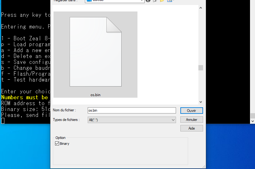
Click on "Open", a popup should now show up, wait until the file finishes transferring.
Once the transfer is finished, the popup window should close itself, and the bootloader will show the message:
Flashing in progress, do not turn off...
Zeal 8-bit OS
The bootloader is an interface to ease flash programming or have multi-boot on the board, but the main operating system is Zeal 8-bit OS. In this section, we will concentrate more on the user interface than on the technical details on it. Of course, you can still find all the technical and implementation details on the Github project.
Once booted, you should see a similar boilerplate:
Zeal 8-bit OS v0.2.0-20-ge684039
Build time: 2023-03-03 21:29
(I) Driver: SER0 init success
(I) Driver: GPIO init success
(I) Driver: I2C0 init success
(I) Driver: KEYB init success
(I) Driver: RDSK init success
(I) Driver: DSK1 init success
(W) Time unavailable
Kernel ready.
Loading A:/init.bin  @4000

A:/>
The first line shows the current version of the operating system, including the commit number corresponding to its source code on Github.
The lines following the build time describes the drivers that have been loaded into the kernel. A green line shows a success, a red line shows a failure and a yellow line shows a warning.
For example, the line Time unavailable reveals that there are no timer drivers loaded into the kernel, so it will not be possible to use gettime and settime syscalls, which are used to measure the elapsed time.
As you can see, the last line presents a prompt with the current path, which is A:/, the default disk, in our case here. This prompt is not offered by the kernel or the operating system but by the initial program called init.bin. This file is loaded from the default disk, A:/. By default, this disk is a virtual disk that is present on the ROM (NOR Flash). In other words, its content is a table of files flashed to the ROM/NOR Flash, but mounted, and seen, as a read-only disk by the kernel. As such, you will not be able to create or remove files inside it. Another disk is available, disk B:/, which corresponds to the I2C EEPROM. It is using ZealFS file system, so it can be used in both read and write.
Back to init.bin, it can be seen as a busybox for Zeal 8-bit OS: it contains several built-in commands that will invoke the kernel to perform operations. By typing help, you will have a list of the built-in commands, which currently includes:
cd: change current directory, the parameter following it can be a disk, likeA:/orB:/, or a relative path, like.., or an absolute path for the current disk, like/my_dir.cp: copy a file from one place to another, the source and destination can be on two different disks. The destination disk must be writable.date: display the current date saved in the RTCexec: execute a binary program located in the current directory, the syntax isexec <name_of_file.bin>help: show the list of commandsless: show the content of a fileload: load a binary program from the UART, this command takes the size, in bytes, of the program to load as a parameter, can be given in decimal,load 50, or hexadecimalload 0x32. Once executed, the program will be waiting for that amount of bytes on the UART. It will then directly jump to the program to execute itls: list the files in the current directorymkdir: create a directory in the current directoryrm: remove a file or an empty directory from the current directory
More commands may be present depending on the version of Zeal 8-bit OS you are executing.
For example, in order to copy a file from disk A:/ to disk B:/ and show its content, you can type the following commands:
A:/> cd B:/
B:/> cp A:/simple.txt newfile.txt
B:/> ls
newfile.txt
B:/> less newfile.txt
[...File content...]
Developing for Zeal 8-bit OS
Currently, apart from the command line interface, not many programs are available on Zeal 8-bit OS, so why not create your first program? Let's have a quick look at how to do this.
There are two ways to do so at the moment: use C with SDCC, or use assembly and z88dk-z80asm. You will need to do the following:
- Clone Zeal 8-bit OS Github project from here https://github.com/Zeal8bit/Zeal-8-bit-OS.
- In case you want to program in C, you will need to install SDCC, at least
v4.2.0. Check their project on their official website. - In case you want to program in assembly, you will need to install
z88dk-z80asm. Check their project on their official Github page. It is also possible to download binary builds in case you are using Windows or Mac OS, check their nightly build page.
After everything is ready, check the directory kernel_header/examples/sdcc or kernel_header/examples/z88dk-z80asm to see an example program for C and assembly respectively. These programs can be used as templates as they also provide a Makefile that will ease their configuration and compilation. For more details about what they do and how to compile them, check the README files present in the directories given above.
After compiling a program, the simplest way for you to execute it on Zeal 8-bit OS is to load it thanks to the load <size_in_bytes> command. Then, when the prompt will be waiting for the program to be sent, follow the instructions given in the section Send files.
Enjoy!
Now you know how to access the monitor, how the bootloader works, how Zeal 8-bit OS work, how to flash and reflash the ROM, you are ready to develop and enjoy the system!
If you need assistance or if you have any further question or suggestion, you can contact me either by email (check About page) or on my Discord server.
Troubleshooting
Q: Where is the technical reference manual or the hardware documentation?
A: The hardware manual is currently being written, it will be published as soon as possible.
Q: My board is not powering on, despite the fact that I plugged a USB-C cable, what could be the problem?
A: Because of the type of USB-C connector present on Zeal 8-bit Computer, power supplies that don't output 5V by "default" will not work. As such, computer power supplies may not work, even if it's a USB Type-C plug. Try with another power supply, such as a phone one. If you don't have any other, try with a computer USB port.
Q: I tried with another power supply, the board is still not powering on, why?
A: If you are sure the power supply is working properly, check if the fuse is burned, use a multimeter for this, in continuity mode. If the fuse is working, plug the power in and check the voltage across the fuse. The USB-C connector case is connected to ground, you can use it to measure the voltage. You should read 5V. If that's not the case, have you pressed the switch J1?
Q: Why shouldn't I power the computer from the extension port or the user port?
A: When powering the computer from the USB-C port, it first goes to a fuse, that protects it from short-circuit. If you power the computer from an extension port, through the 5V pins, the fuse will not be effective, thus, any short-circuit will provoke irreversible damage to the components and the board itself.
Q: What is the jumper JP2, near the RTC, used for?
A: The JP2 was mainly here for potential future usage. In fact, it connects the RTC's output square wave signal to the Z80 PIO H-Blank signal. As such, when no video card is connected, the RTC could be used as a timer. This has not been implemented yet.
Q: In the bootloader, when I test the hardware, the RTC shows "Disable", why?
A: It's a good sign! It means that the RTC chip responded to the request made by the CPU. However, the RTC is not currently counting anything, it is in idle mode. The bootloader will automatically send a command to the RTC to enable it. If you restart another hardware test right after the first one, you should see the current time stored on the chip.
In the case where the test always shows "Disable" even after several tries, the battery may be dead, try replacing it.
Q: In the bootloader, when I test the hardware, the RTC returns an error, why?
A: You will need to plug a battery in the socket in order to get the RTC chip to work. In fact, if no battery is connected, the BAT+ pin is left floating, which is not a valid state for the component. If you still want to use the RTC without a battery, you can connect the BAT+ pin to ground, ideally with a resistor (20kOhm or bigger).
Q: Can I type decimal values in the bootloader?
A: When providing addresses to the bootloader, the hexadecimal representation must be given. No need to prefix the numbers with 0x.
Q: In Zeal 8-bit OS, I type on my monitor but no character is shown on screen! Why?
A: Contrary to the bootloader, Zeal 8-bit OS doesn't support UART as the standard input (this is in development), you can follow the advancement of the project on github. At the moment, a PS/2 keyboard is required to type anything on the OS.
Q: What commands can we use on Zeal 8-bit OS? Are these part of the Operating System?
A: You can get the list of all the commands available by simply typing "help". These are not part of the system, they are part of the software, called init that is executed by the kernel after initialization.
Q: How can I load a program from UART on Zeal 8-bit OS?
A: You an load a program thanks to load command. Pass the size of the binary to load as a parameter, which can be in decimal or hexadecimal, and then send your file the same way it is described above. The program will automatically jump to it after receiving it. The binary must be assembled with an ORG address of 0x4000.
For example:
load 512
or
load 0x200
to receive and execute a program of size 512 bytes.
Q: Does Zeal 8-bit OS provide a debugger or such mechanism to develop?
A: The OS currently doesn't provide such thing, however, you can find a working emulator and debugger here. This emulator is fully open-source, you can find it here.
Q: What can I do in Zeal 8-bit OS?
A: Not much at the moment, the OS is still under development. In fact, there are still several things to implement, such as a R/W file system to really have something that can be used. There are also several drivers that need improvement and implementation for Zeal 8-bit Computer. If you would like to take part in the development, you can check the github repo, or contact me by email or on Discord.
Q: Why is the Video Card connector not populated?
A: As you may have seen in some of my videos, the version I use does have a connector. However, after testing it for months, it may not be the best stable option. I am still considering which one to use instead. As this will require a lot of testing, and thus, time, I preferred to not populate the connector for the moment. In the future, when Zeal 8-bit Video Card will be available, that connector will be provided.
Q: When will Zeal 8-bit Video Card board be available?
A: Currently, the board is still under development, on both the hardware side and the software side. As soon as Zeal 8-bit Computer grows and have active development, I will be able to spend more time on that video board.