18
Extension port
The user port is convenient to interface microcontrollers or devices that can communicate over UART, I2C or GPIOs, they don't need any particular setup other than plugging the right pins together.
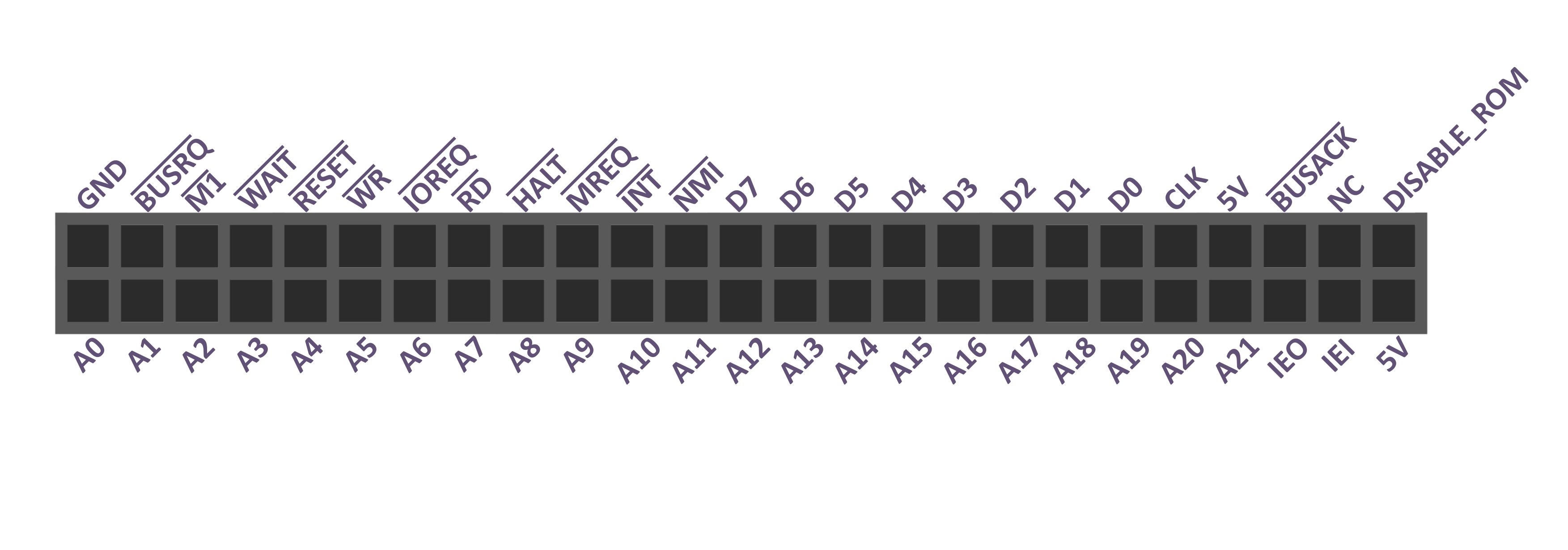
However, this port becomes quickly limited when it comes to interfacing a component with the Z80 CPU. This is why Zeal 8-bit Computer also presents an extension port, referenced J2, which gives access to all the signals that are internally used by the components on the motherboard.
The pinout of the extension port is as follows (front view):

The signals are:
- $5V$ and $Gnd$: power output. The current drawn by the extension board must not exceed 1A, else the fuse
F1will blow. - $A_0$ to $A_{21}$: address bus, corresponding to the current byte being accessed (read or written) on the 4MB physical address space by the CPU. The lines $A_0$ to $A_{13}$ are coming from the Z80 CPU directly, whereas the lines $A_{14}$ to $A_{21}$ are routed from the MMU.
- $D_0$ to $D_7$: data bus. During a write, specify the value of the byte to write to the current address, driven by the CPU. During a read, it is driven by the component the CPU is trying to read (ROM, RAM, extension board, etc...)
- $IEO$ and $IEI$: signals connected to the Z80 PIO, used to form a daisy chain of devices that can interrupt the Z80 CPU while having a concept of priority. It is advised to use these pins rather than $\overline{INT}$ directly. $IEI$ is internally pulled-up with a 1kΩ resistor, it is not required to add an external one. Check the Z80 PIO section for more information about these signals. These lines are always called $DATA\ 0$...$DATA\ 7$ in this documentation.
- $\overline{INT}$: open-drain interrupt signal, connected to the Z80 PIO, the Z80 CPU and the internal I²C port, it can be pulled low by the extension board to notify the CPU that an interrupt is requested. Keep in mind that Zeal 8-bit Computer is meant to be used in interrupt mode 2, just like the PIO. This signal is already pulled high internally with a 1kΩ resistor, it is not required to add an external one.
- $\overline{NMI}$: open-drain non-maskable interrupt signal, connected the Z80 CPU. It can be pulled low by the extension board to notify the CPU that a non-maskable interrupt is requested. This signal is already pulled high internally with a 1kΩ resistor, it is not required to add an external one. It is unused on Zeal 8-bit Computer motherboard.
- $CLK$: clock signal that comes from the active 10MHz oscillator. Check the Clock circuit section for more information.
- $\overline{RESET}$: reset signal coming from the Reset circuit, active on boot up or when the reset button, referenced
SW2, is manually pressed. - $\overline{BUSRQ}$, $\overline{BUSACK}$, $\overline{M1}$, $\overline{WAIT}$, $\overline{WR}$, $\overline{RD}$, $\overline{IOREQ}$, $\overline{HALT}$, $\overline{MREQ}$: signals that are connected to the Z80 CPU, all the details about them can be found in the Z80 CPU section.
- $ROM\_DISABLE$: signal that can be tied to $V_{cc}$ (5V) to disable the internal ROM. Keep in mind that by doing this, the extension board must have a device that will be mapped at
0x000000, which is the physical address of the ROM. To keep the internal ROM active, this pin must be left unconnected.