I²C Real-time Clock (RTC)
15.1 Overview
Nowadays, all our computers have one key feature that sounds obvious to have: a real-time clock, or RTC. This hardware component lets computers keep track of the current date, even when powered off.
On most retro computers from the late 70s and 80s, no RTC was present. While it doesn't seem like a very critical feature to have, it may raise some issues as soon as we try to interface one with a modern computer. For example, common file systems have a date field that records the date of creation and/or modification of a file or directory. As such, if we want our 8-bit computers to generate this information for new files, we need a way to keep tracking the current date and time.
15.2 Hardware implementation
On Zeal 8-bit Computer, the RTC is implemented with the DS1307 integrated circuit, referenced U13 on the PCB. This circuit was chosen because of its small form factor and its simplicity of programming as it is also using the I²C protocol.
This RTC requires two external components to be able to keep track of the time:
- A crystal oscillator on the PCB, marked at 32.768KHz, with a capacitance of 12.5pF
- A 3V backup battery on the PCB, to keep the time counting when the main power supply is off
The backup battery socket installed on Zeal 8-bit Computer, referenced BT1, is compatible with any CR20xx standard battery, including CR2016, CR2025, and CR2032. The only difference between these batteries is their thickness and their capacity.
When the computer is powered on, the backup battery will not be used by the RTC. In fact, internally, it has a built-in circuit that will detect power failures and will automatically switch to the backup battery only when the main power is not connected anymore.
Overall, here is the pinout of the integrated circuit:
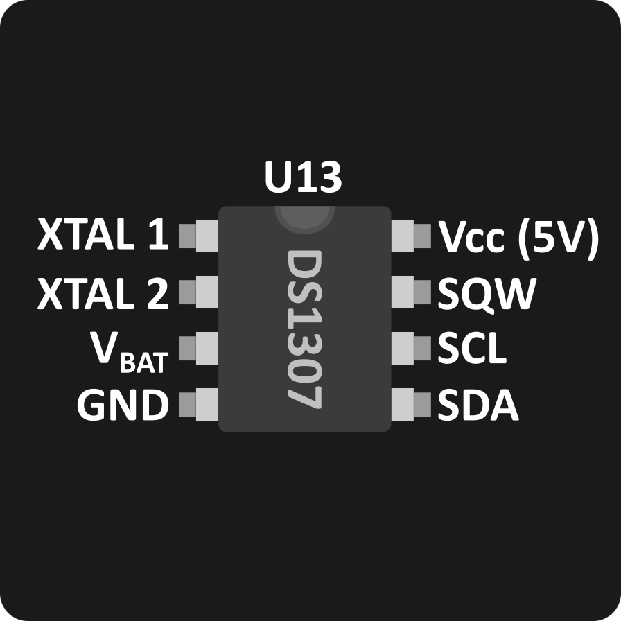
The signals are the following:
- $XTAL1$ and $XTAL2$: connected to the 32.768KHz crystal oscillator referenced
Y1on the PCB - $V_{BAT}$: + connector coming from the back battery connector
- $Vcc$ and $Gnd$: main power supply (5V)
- $SQW$: open-drain square wave signal, check the Bonus feature section for more information
- $SCL$ and $SDA$: I²C clock and data signals respectively, check the Inter-Integrated Circuit (I²C) section for more info.
The RTC doesn't present any pins to configure its slave address. Indeed, its 7-bit address is hardcoded to be 0x68.
⚠️ Warning
The RTC requires $V_{BAT}$ to always be set to a known value and never left floating. Thus, communicating with the RTC when no battery is installed may lead to errors. In such case and in the absence of battery, connect a resistor (~20kΩ) between $V_{BAT}$ and $Gnd$.
15.3 Communicating with the RTC
The registers
The RTC has internally been organized around 7 registers which represent the seconds, the minutes, the hours, the day, the date, the month and the year respectively. All these registers contain a value represented in Binary-Coded Decimal or BCD.
Binary-Coded Decimal is a way of representing decimal numbers, which is the representation of numbers we use daily, by converting each digit to its hexadecimal equivalent. In other words, instead of converting the whole decimal number to hexadecimal, we will convert each of the digits to hexadecimal and concatenate them.
For example, the BCD representation of the decimal number 59 is 0x59 (and not 0x3b)
The 7 registers are described in the following table:
Table 2 Timekeeper Registers
| Address | Bit 7 | Bit 6 | Bit 5 | Bit 4 | Bit 3 | Bit 2 | Bit 1 | Bit 0 | Name | Range |
|---|---|---|---|---|---|---|---|---|---|---|
| 0x00 | HALT1 | 10 Seconds | Seconds | Seconds | 00-59 | |||||
| 0x01 | 0 | 10 Minutes | Minutes | Minutes | 00-59 | |||||
| 0x02 | 0 | 12/24 mode2 | 10 Hour or PM/AM | 10 Hour | Hours | Hours | 1–12+AM/PM 24 00–23 | |||
| 0x03 | 0 | 0 | 0 | 0 | 0 | Days | Day | 01-07 | ||
| 0x04 | 0 | 0 | 10 Date | Date | Day | 01-31 | ||||
| 0x05 | 0 | 0 | 0 | 10 month | Month | Month | 01-12 | |||
| 0x06 | 10 Year | Year | Year | 00-99 | ||||||
Small notes about the following bits:
HALT$^1$: when this bit is 1, the clock is halted, which reduces the power consumption but stops the internal time.12/24 mode$^2$: when this bit, is 1, 12-hour mode is enabled. In this mode, bit 5 isPMwhen 1,AMwhen 0. When this bit is 0, the 24-hour mode is enabled. In this mode, bit 5 represents the hours with bit 4 (now ranging from 00 to 23). Whenever the mode is switched, the hours much be manually updated.
Reading and writing the registers
Communicating with the RTC consists in retrieving or writing these registers. Similarly to the EEPROM we saw earlier, there are three ways to communicate with the RTC:
- Write thanks to I²C write transactions
- Read in Random Address mode, thanks to I²C write-read transactions
- Read in Current Address mode, thanks to I²C read transactions
For example, to enable the clock, we need to unset register 0 bit 7. To do so, we need to perform an I²C write transaction as follows:
- Generate a START condition
- Send device address,
0x68, followed by write bit (0) - Make sure the device acknowledged (SDA pulled low)
- Send the address of the register to write,
0x00in this case - Make sure the device acknowledged
- Send the new value of the register,
0x00again, which will also resent the seconds to 0 - Make sure the device acknowledged
- Generate a STOP condition
This is also the way to set or update the clock values after a data loss or a clock stop.
To read the values of the RTC, we can directly perform a read without specifying the register to read or perform a write-read to specify the register to start reading from. In both cases, it is possible to read several registers with a single transaction.
We will only consider the second case here. For example, if we want to read all the 7 registers, starting from 0, we need to perform an I²C write-read transaction:
- Generate a START condition
- Send device address,
0x68, followed by write bit (0) - Make sure the device acknowledged (SDA pulled low)
- Send the address of the register to start reading from,
0x00in this case - Make sure the device acknowledged
- Generate a (RE)START condition again (without a STOP condition!)
- Send device address,
0x68, followed by read bit (1) - Make sure the device acknowledged
- Receive the first byte, which is the register 0 value, and acknowledge by pulling SDA low during one clock cycle
- Do the same for registers 1, 2, 3, 4, 5
- Receive the sixth byte, which is the register 6 value, but do not acknowledge by keeping SDA high during one clock cycle
- Generate a STOP condition
Diagrams for these transactions are available in the previous I²C EEPROM section, check it for more information.
⚠️ Warning
The RTC may be very sensitive to SDA and SCL timings. Even though the overall frequency respects the limitation given by its datasheet, it may not respond with ACK bits after sending its slave address. This is may be due to the timing at which the chip internally latches SDA line when SCL goes high. This is unfortunately not documented.
To fix this issue, make sure SCL clock signal has a 50% duty-cycle (stays low for the same duration as it stays high). More importantly, make sure SDA line is set to the required state before setting SCL line to high (and not at the same time).
15.4 Bonus features
The RTC integrated circuit provides some additional features that can be used optionally.
NVRAM
The first feature is RAM, the chip provides 56 bytes that can be used freely. Its main purpose is to store data that will be kept even after resets as it will also be powered by the battery. As such, this portion can be considered non-volatile as long as the battery still has power.
The NVRAM starts at address 0x08 and goes up to 0x3F included. Communicating with this portion of RAM works the same way as the other registers, described in the previous paragraph.
Square wave generator
Another feature offered by the RTC chip is a square wave generator. Indeed, as shown in the previous image of the pinout, the circuit can output a square wave signal on pin $SQW$.
This pin can also be forced to 0 or 1 depending on how it is configured by the software. The register 0x07 is responsible for this feature, it is organized as follows:
| Bit 7 | Bit 6 | Bit 5 | Bit 4 | Bit 3 | Bit 2 | Bit 1 | Bit 0 |
|---|---|---|---|---|---|---|---|
| OUT | 0 | SQWE | 0 | Rate Select | |||
When SQWE is set to 1, the square wave generation is enabled, at the frequency depends on the value of Rate Select:
| Rate Select value | Output frequency |
|---|---|
| 0 | 1Hz |
| 1 | 4.096KHz |
| 2 | 8.192kHz |
| 3 | 32.768kHz |
In that case, the OUT bit will be ignored.
When SQWE is set to 0, the square wave generation is disabled, and the output on $SQW$ is the same as OUT bit: high when OUT is 1, low when OUT is 0.
It is important to note that the $SQW$ pint is in open-drain configuration! In other words, it is pulled to $Gnd$ when it equals 0, but it is left floating when it equals 1.
Thanks to this, it is possible to make use of this pin to make a hardware timer. Indeed, by connecting the pins of the jumper referenced JP2 on Zeal 8-bit Computer, the $SQW$ pin will be connected to PIO's H-SYNC IN signal. That signal is also an open-drain signal that is pulled up by a resistor network referenced RN3.
As such, whenever the square wave signal goes low, an interrupt can be requested by the PIO, the software can therefore keep track of time in case it needs to perform some benchmarks or simply evaluate the elapsed time between two operations.
⚠️ Warning
It is not advised to connect
JP2jumper if a video board is connected on the video port and theJP4jumper is connected to accept H-blank signals from it.While this doesn't present any hardware risks of short-circuit thanks to the open-drain configuration, in the software it may be tricky to determine the real source of the H-SYNC IN signal interrupt as it will be shared between the RTC timer and the external video board.