Power-on and reset circuit
4.1 Overview
Zeal 8-bit Computer requires a stable 5V power supply in order to run properly. It must be delivered through the USB Type-C port, referenced J1, available on the board.
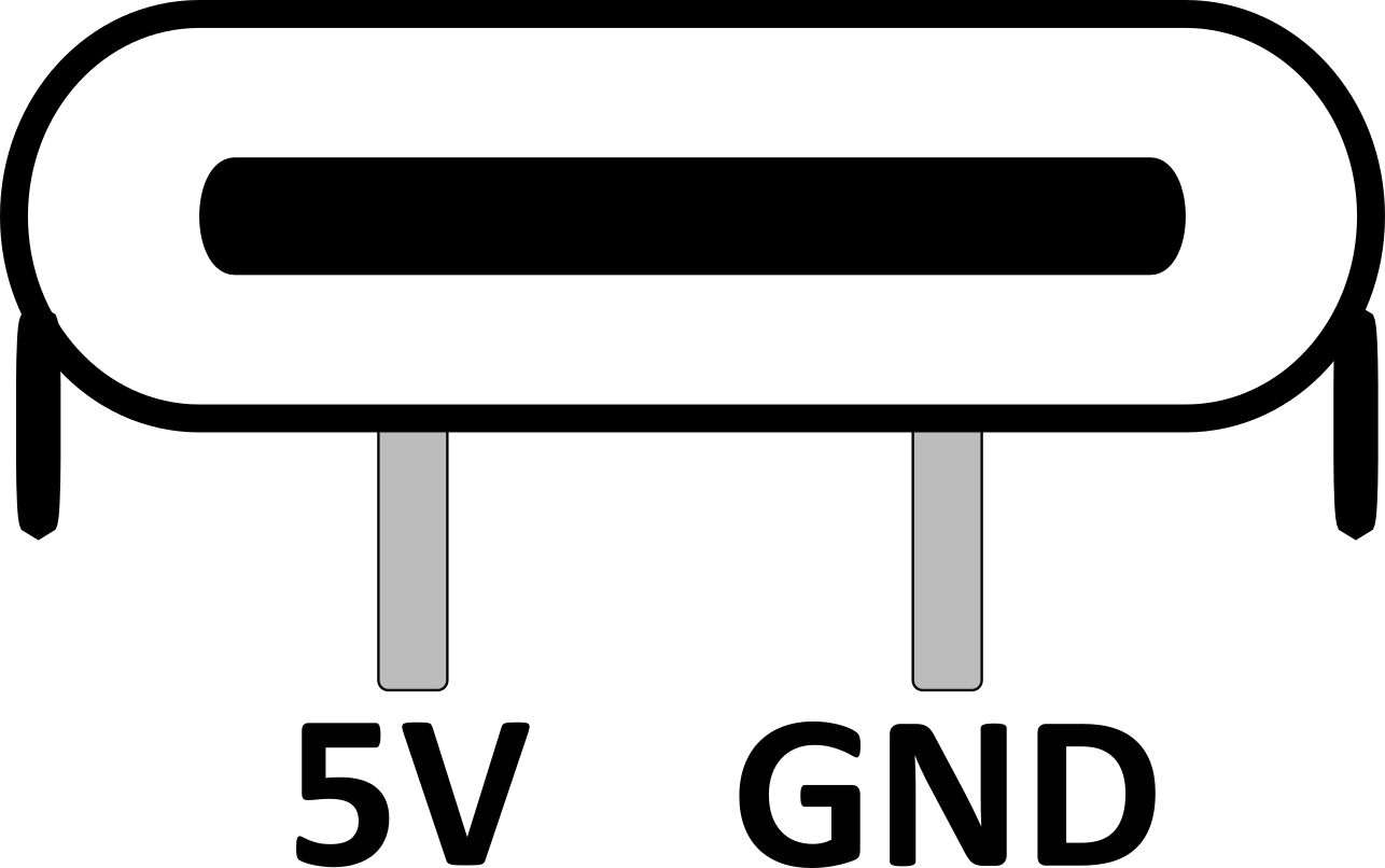
This power port is a 2-pin USB-C port, the shield is connected to ground. From the front view, the left pin is 5V and the right pin is ground.
4.2 Powering on
Make sure the DC power adapter and the USB Type-C cable can deliver at least 500mAh. As the power consumption also depends on the number of peripherals connected to the board, the adapter should ideally be marked as able to deliver at least 1A.
The switch referenced SW1 acts as a power switch. As soon as it is pushed, the power will be delivered to the components through the fuse referenced F1.
Indeed, the fuse is here as protection in case a short circuit happens due to internal or external components. The fuse is rated to 1A. Thus, if the current drawn by the whole computer goes above this limit, the fuse will blow.
If the fuse blows, it must be replaced. It can be taken out of its socket and replaced without the need for soldering or de-soldering.
4.3 Reset signal
When power is provided to the board, the reset signal line going to the processor will be held low for at least 150 milliseconds. This mechanism is necessary to initialize the processor and the memory management unit.
To achieve this, the MCP130 supervisory circuit, referenced U1 on the board, is used. Its role is to hold the RESET line low until the input voltage stabilizes. As soon as the threshold voltage is reached, the reset line is kept low for around 350ms before going high.
The supervisory circuit may be accompanied by a pull-up resistor, between 5kΩ and 10kΩ, referenced R2. When the MCP120 is used as the supervisory circuit, this resistor is strictly necessary. However, if the MCP130 is used, it is not necessary as the latter already provides an internal resistor.
Please refer to their datasheet for more information.
4.4 Reset switch
The reset signal line is also connected to a switch, named reset switch and referenced SW2. It lets users manually trigger a hardware reset, without the need to unplug and re-plug the USB-C power cable.
Note that this won't affect the supervisory circuit, nor trigger a short-circuit because the reset line is an open-drain signal. So, the reset line must always be connected to Vcc (5V) through a pull-up resistor.
4.5 Reset circuit diagram
