Logic Glue
8.1 Overview
Zeal 8-bit Computer has several components that can interact with the CPU. They can be related to memory, like the RAM or ROM, or I/O, like the keyboard or Z80 PIO.
From a software point of view, it is fairly easy to distinguish how to talk to each of them: they have different addresses. The addresses attributed to each component depend on the way the hardware decodes and distributes them.
8.2 Hardware description
On 8-bit computers, all the components the CPU needs to interact with are sharing at least two buses: the address bus (unidirectional) and the data bus (bidirectional). If we consider that signals such as $\overline{RD}$, $\overline{WR}$, $\overline{IOREQ}$, $\overline{MREQ}$, compose a complementary "signal" bus, then each component must also share this one.
As such, it is clear that components must not communicate at the same time, at each memory or I/O request done by the processor, at most one component must respond by reading or writing a byte on the DATA bus. This is why we need an entity responsible for that: the logic glue.
The role of the logic glue is to assign a given address or range of address to a single component, thank to this, it connects (or glues) the components to the CPU.
8.3 Hardware implementation
On Zeal 8-bit Computer, the logic glue is implemented with a Programmable Logic Device, or PLD. They are very convenient as they let us create versatile and flexible logic functions that would, else, require several NOT, AND, OR logic chips. Because all the logic is confined within a single chip, it doesn't only make the required space on the PCB smaller, but it also makes the propagation delay, i.e. the time required by the internal logic to generate and output the pre-programmed signals, much faster than using several logic chips.
The PLD used on Zeal 8-bit Computer motherboard is an ATF16V8B-15PU, it has a propagation delay of 15ns. On the PCB it is referenced U6. For more information about its electrical and physical characteristics, check its datasheet.
The chip is pre-programmed to have the following pinout:
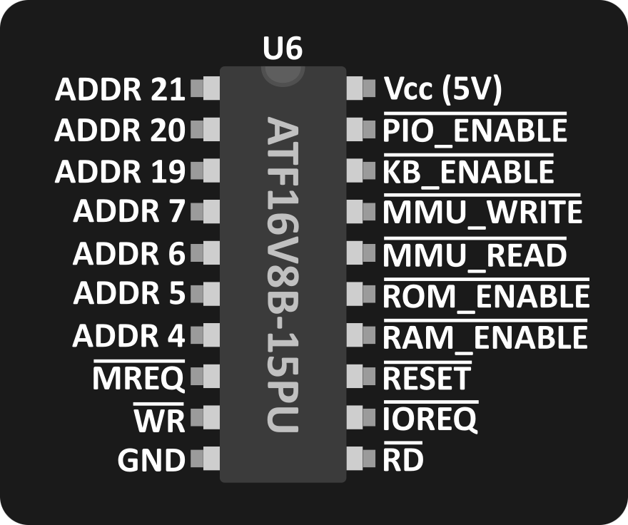
The output signals are the following:
- $\overline{PIO\_ENABLE}$: allows the Z80 PIO to read or write a byte to DATA bus. Active during an I/O request, when the lowest 8-bit of the physical address is between [
0xD0,0xDF] - $\overline{KB\_ENABLE}$: allows the Keyboard buffer(s) to output a byte on the DATA bus. Active during an I/O request, when the lowest 8-bit of the physical address is between [
0xE0,0xEF]. - $\overline{MMU\_WRITE}$: allows the MMU to read the byte from the DATA bus. Used to modify the value of an MMU page. Active during an I/O request, when the lowest 8-bit of the physical address is between [
0xF0,0xF3] and CPU $\overline{WR}$ signal is active. Also active during reset. - $\overline{MMU\_READ}$: allows the MMU to output a byte on the DATA. Used to read the value of an MMU page. Active during an I/O request, when the lowest 8-bit of the physical address is between [
0xF0,0xF3] and CPU $\overline{RD}$ signal is active. - $\overline{ROM\_ENABLE}$: allows the ROM to write a byte to DATA bus. Active during a memory request when, the physical address is between [
0x00000,0x7FFFF] - $\overline{RAM\_ENABLE}$: allows the RAM to read or write a byte to DATA bus. Active during a memory request, when the physical address is between [
0x80000,0xFFFFF]
The input signals need several inputs:
- ${ADDR\_21}$ to ${ADDR\_19}$: signals coming from the MMU, representing the 3 highest bits of the physical address for the current (memory) request. Ignored when $\overline{IORQ}$ signal is active.
- ${ADDR\_7}$ to ${ADDR\_4}$: signals coming from the CPU, representing the highest bits of the physical address for the current I/O request. Ignored when $\overline{MREQ}$ signal is active.
- $\overline{MREQ}$: signal coming from the CPU, active when the CPU is performing a memory request.
- $\overline{IORQ}$: signal coming from the CPU, active when the CPU is performing an I/O request.
- $\overline{WR}$: signal coming from the CPU, active when the CPU is performing a write.
- $\overline{RD}$: signal coming from the CPU, active when the CPU is performing a read.
- $\overline{RESET}$: signal coming from the power circuit, active when a reset is being performed. Used to initialize the MMU on reset.
8.4 Hardware dependencies and timing
From the input signals described above, we can see that the PLD input signals depend on two entities: the MMU and CPU. This means that to calculate the complete propagation delay of the logic glue, we first need to determine the delay the input signals themselves will take to reach the PLD.
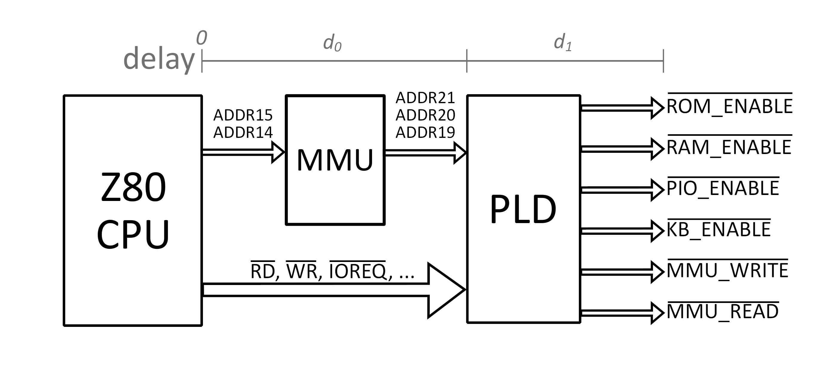
In practice, $d_0$ value is typically 16ns, whereas $d_1$ is typically 15ns.
All the details about the delay and timings are explained in the official datasheet.
8.5 Maintenance
It is possible to replace the AT16V8B PLd present on the board with another one or even a GAL16V8b. However, make sure that the timings are matching the original one: 15ns propagation delay.
Of course, you will also need to program the PLD before installing it on the motherboard, you will find the JED file to flash on it at https://zeal8bit.com/bin/ZealLogicglue.jed