User port
The PIO provides several signals that are used internally on Zeal 8-bit Computer motherboard, as we saw in the previous sections. Moreover, it also presents signals that are meant to be used by the user himself.
To give access to these signals, a user port referenced J3 is provided on the motherboard. It is a standard 2x8 2.54mm female port, its pinout is as followed (front-view):
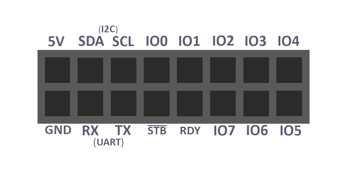
The signals are the following:
- 5V and $Gnd$: power output. The current drawn by the external components must not exceed 1A, else the fuse
F1will blow. - $SDA$ and $SCL$: open-drain I²C signals generated from the internal circuit as explained in the I2C section. These signals are pulled to 5V with 4.7kΩ resistors, so no need to use external pull-up
- $RX$: (input) UART receive signal, connected to the Z80 PIO through a 512Ω resistor
- $TX$: (output) UART transmit signal, connected to the Z80 PIO through a 512Ω resistor
- $IO_0$ to $IO_7$: General purpose I/Os that can be used freely by the user.
- $\overline{STB}$ and $RDY$: handshake signals for the 8-bit general purpose I/Os, more information about these two signals in the PIO section
⚠️ Warning
For all the signal pins listed above, in input mode, a logic high is represented by a minimum of 2V and a maximum of 5V, while an input low is represented by at most 0.8V.
In output mode, a logic high will be set to 5V, while a logic low will be set to at most 0.4V.
Make sure to never exceed the maximum voltage of 5V for all the pins, and to always connect to their signals components that are 5V-tolerant, to avoid any damage.